Ultra-Thin Flexible P-type HJT

Flexible HJT Solar Cell Module

Heliofold P-type HJT is a lightweight flexible solar cell module for customers evaluating mechanically compliant photovoltaic surfaces, high specific power, and flexible photovoltaic architectures.

Product Overview

A flexible HJT cell route for lightweight photovoltaic stack evaluation.

P-type HJT adds a cell-level product to the Heliofold material portfolio. It combines an ultra-thin silicon HJT cell with a symmetric flexible module concept, giving integrators a physical platform for bending, bifacial response, and stack-architecture screening.

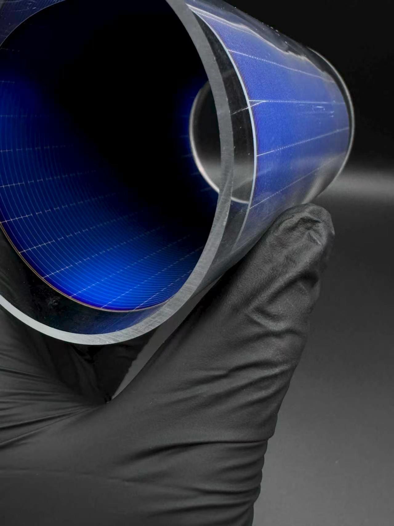
P-type HJT is presented as a photovoltaic cell module rather than as a standalone protection material. The product should therefore be evaluated together with interconnect design, electrical stringing, front/back protection, bend radius, thermal cycling, and mission-level qualification assumptions.

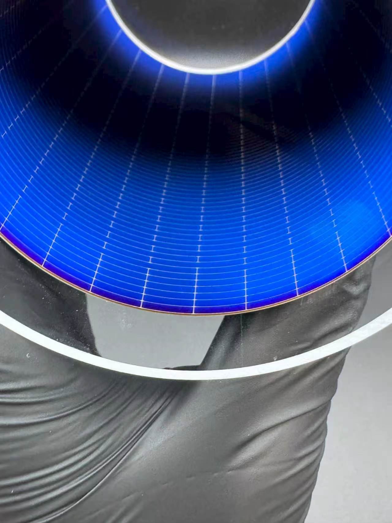
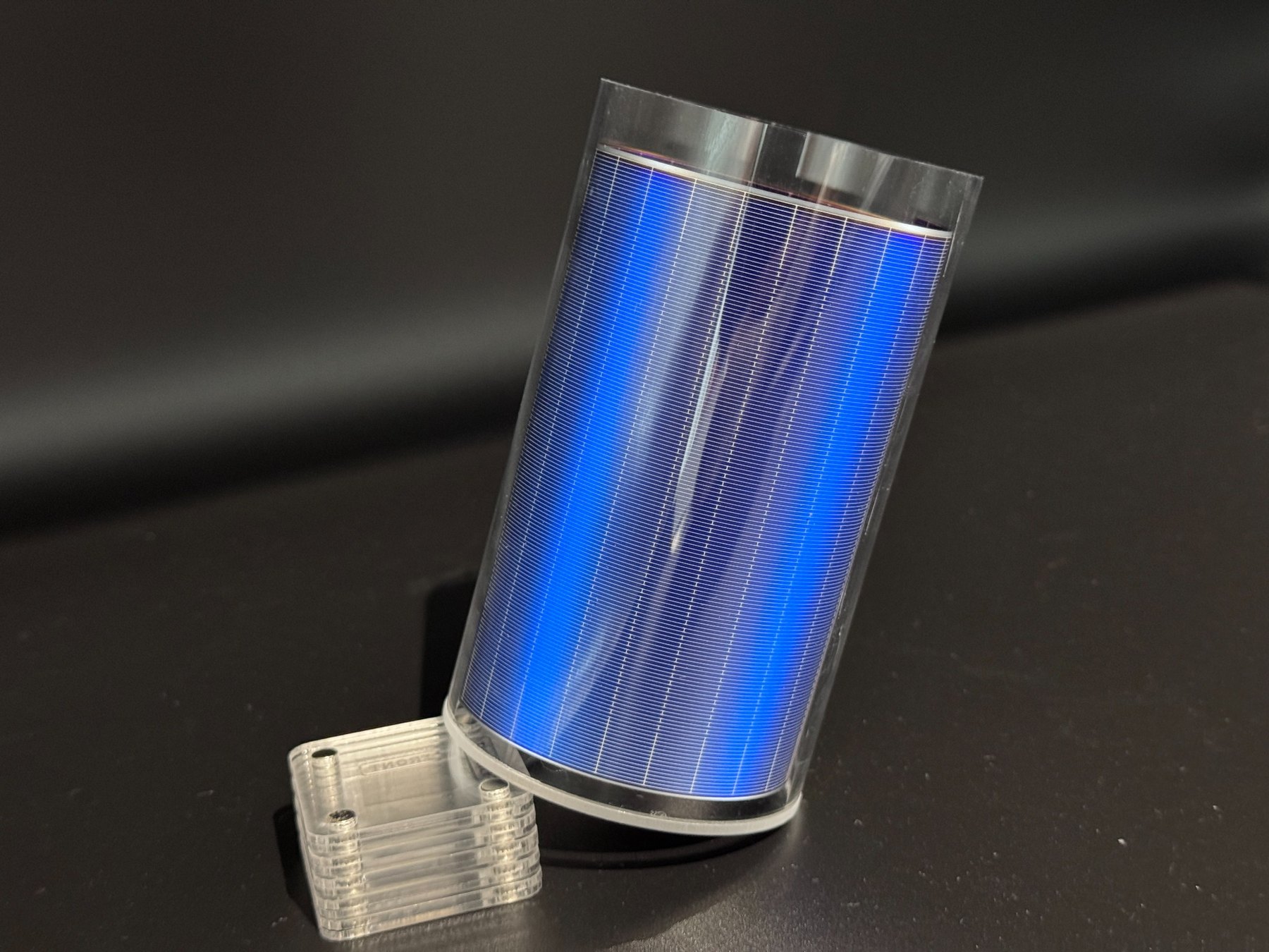
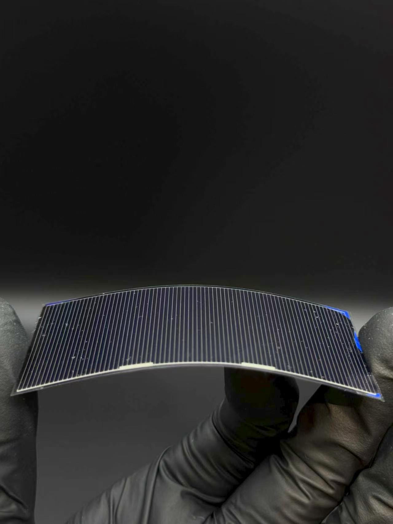
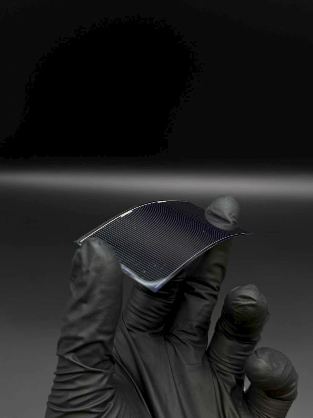
  • Flexible cell platform65 µm cell thickness supports mechanically compliant demonstrators and curved form-factor screening.
  • Bifacial architectureA symmetric front/rear module design keeps both sides available for optical and environmental evaluation.
  • High specific power targetThe data sheet lists ≥750 W/kg BOL specific power, positioning the P-type HJT module for lightweight array trade studies.

P-type HJT should be evaluated at module and array-stack level. Cell interconnects, adhesive route, bend radius, deployment mechanics, environmental qualification, and final electrical architecture remain customer or integrator defined.

HJT flexible solar cell module under gloved handling
P-type HJT flexible cell module P-type silicon HJT sample shown under controlled handling.

Application Note

Use P-type HJT as a cell platform, not just as a cover-material substitution.

The technical premise is a bifacial HJT photovoltaic element with a flexible front/rear protective structure. The commercial value is strongest when the cell is used to reduce mass and increase mechanical compliance at the stack level, while preserving the customer’s ability to define the array architecture.

Integration premise

P-type HJT should be framed as an ultra-thin silicon HJT cell module for stack studies where rigid glass-cell assumptions are too limiting. The page avoids claiming a complete flight-qualified array because deployment hardware, interconnect design, bypass protection, bonding route, and electrical layout are system-level decisions.

For near-term customer conversations, the main qualification questions are mechanical: bend radius, handling damage, interconnect strain relief, front/rear encapsulation adhesion, thermal cycling, and optical retention after environmental exposure.

For photovoltaic screening, the relevant baseline is the data-sheet electrical set under AM1.5G conditions: Voc, Jsc, conversion efficiency, and specific power. These should be treated as starting values for customer-side stack qualification rather than as final mission output claims.

The current page uses the supplied P-type silicon HJT technical data sheet as the controlling source for all electrical and physical values.

Technical Data

Heliofold P-type HJT Technical Specifications

Electrical and physical values below follow the supplied P-type silicon HJT technical data sheet. AM1.5G conditions are listed as 1000 W/m2 and 25°C cell temperature.

Cell platform

P-type silicon HJT, 65 µm thickness, and 105 × 210 mm cell dimensions define the physical starting point.

Electrical baseline

0.735 V Voc, 38 mA/cm2 Jsc, and ≥22% conversion efficiency under AM1.5G screening conditions.

Lightweight construction

Bifacial symmetric flexible construction with 293.65 g/m2 areal density and ≥750 W/kg BOL specific power.

CategoryParameterP-type HJT valueUnit
Cell
CellTechnologyP-type Silicon HJT
CellThickness65µm
CellDimensions105 × 210mm
Electrical
ElectricalOpen-circuit voltage, Voc0.735V
ElectricalCurrent density, Jsc38mA/cm2
ElectricalConversion efficiency≥ 22%
Encapsulation
EncapsulationStructureBifacial Symmetric
EncapsulationFront & rear coverFlexible protective film
Physical
PhysicalAreal density293.65g/m2
PhysicalAreal density, alternate expression~0.294kg/m2
PhysicalSpecific power, BOL≥ 750W/kg

Data-sheet condition note: AM1.5G, 1000 W/m2, 25°C cell temperature. Final application performance depends on interconnect design, encapsulation process, bend state, operating temperature, and mission environment.

Evaluation Scope

Qualify P-type HJT through a full stack and mechanics plan.

A credible HJT discussion should start from the customer’s cell integration assumptions, bend mechanics, interconnect strain relief, environmental exposure, and target power architecture.

Bend Mechanics

Define bend radius, repeated flexing, cylindrical mounting assumptions, handling process, and acceptable power loss after mechanical stress.

Electrical Stringing

Clarify tabbing, bus routing, bypass protection, interconnect strain relief, and string-level electrical architecture before array claims are made.

Encapsulation Interface

Confirm front/rear encapsulation integrity, optical retention, edge sealing, surface cleanliness, and compatibility with the selected adhesive or lamination route.

Bifacial Use Case

Decide whether rear-side illumination, albedo, or packaging transparency is part of the intended power model.

Thermal Environment

Evaluate thermal cycling, cell operating temperature, coefficient-of-expansion mismatch, and electrical behavior after environmental exposure.

System Boundary

Deployment hardware, substrate frame, array harnessing, mission qualification, and final end-of-life power output are outside this preliminary product page.

P-type HJT Samples

Sample photographs.

The photographs below show the flexible HJT cell module in cylindrical and bending demonstrations. They are intended to communicate form factor, handling route, and visual identity.

Interior view of a curved HJT flexible solar cell module

Curved P-type HJT interior view

Cylindrical demonstration showing the cell surface and transparent encapsulation geometry.

HJT flexible solar cell module standing on a transparent support

Curved module on support

Sample view emphasizing the curved module form factor and edge protection.

Flexible HJT solar cell sample bent between gloved fingers

Flexible cell bending

Bending demonstration for mechanical-compliance and handling discussions.

Side view of HJT flexible solar cell sample under bend

Edge bending view

Side-angle photograph showing thin cell form factor and bend profile.

Discuss Your HJT Flexible Cell Requirements

Tell us your orbit, target power level, required bend radius, interconnect concept, encapsulation route, and qualification timeline. Heliofold can review how P-type HJT fits your flexible-cell evaluation and integration plan.